Furnace Follies
Most owners will never become an ace furnace-repair person, but having the solutions to the following 10 common maladies (in no particular order or importance) in your “pocket” could make the difference between a nice trip and being sidelined, shivering under a blanket. (Note: The following applies to typical furnaces found in RVs. Hydronic and Truma models are not covered here.)
No. 1: LP-gas Pressure
Inadequate gas pressure will cause short cycling or a faulty ignition. Test the system for proper LP-gas pressure (and regulator integrity) using a manometer. Most people use a dial manometer, which should be 11 inches water column with all the appliances off. While testing the gas pressure, start the furnace ignition procedure to verify that the pressure does not completely drop out, which will indicate that the pressure regulator is defective and needs to be replaced. It’s a good idea to replace the regulator every five years.
If you find yourself far from a service center and do not have access to a manometer, a quick way of checking for a drop in gas pressure is to ignite the burners on your stove and turn the furnace on; if the burner flames drop considerably in size or completely go out, the pressure regulator is likely defective.
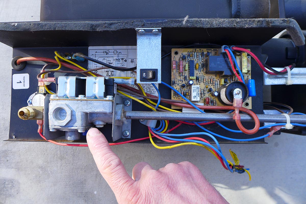
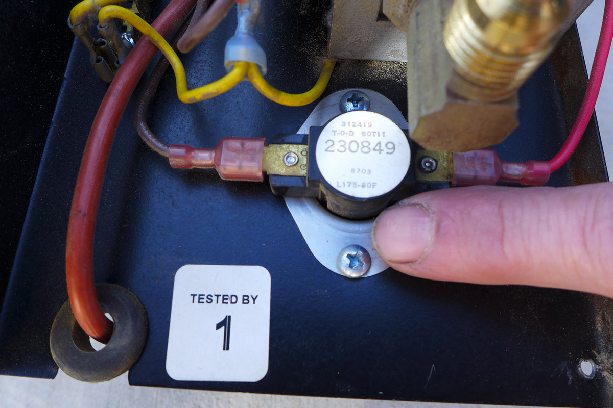
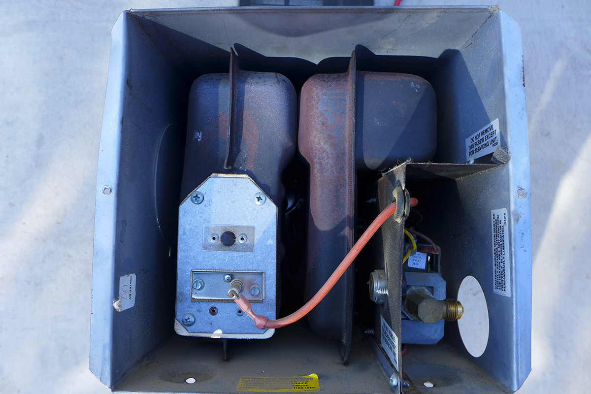
This is a typical gas valve used in most older furnaces, especially Suburban models. There is a tap at the bottom of the valve allowing you to diagnose low pressure problems with a manometer.
No. 2: Home Sweet Home — for Bugs
Mud daubers love the smell of propane and will nest in the intake or discharge pipes, creating a blockage. (Of course, debris can also cause a similar problem.) Using a bright flashlight, look into both pipes to detect any blockage. If the blockage is deep into the system — normally a problem caused by a mud dauber nest attached a blower wheel — you will not be able to see an obstruction from the outside. If you suspect there is a mud dauber nest inside the blower wheel, it will be necessary to remove the furnace and dismantle the blower assembly.
Another possible blockage could be traced to bug screens attached to the outside of the furnace at the intake and discharge ports. Manufacturers do not recommend these as they can impede air intake and discharge if the screens are allowed to plug up. If you insist on using these screens, make it a point to inspect the surface for blockage on a regular basis.
No. 3: The Furnace Won’t Come On
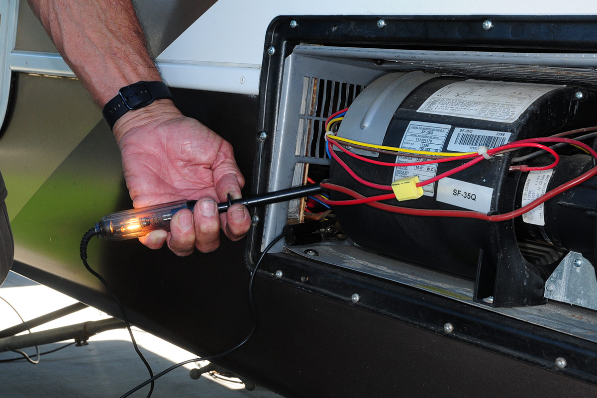
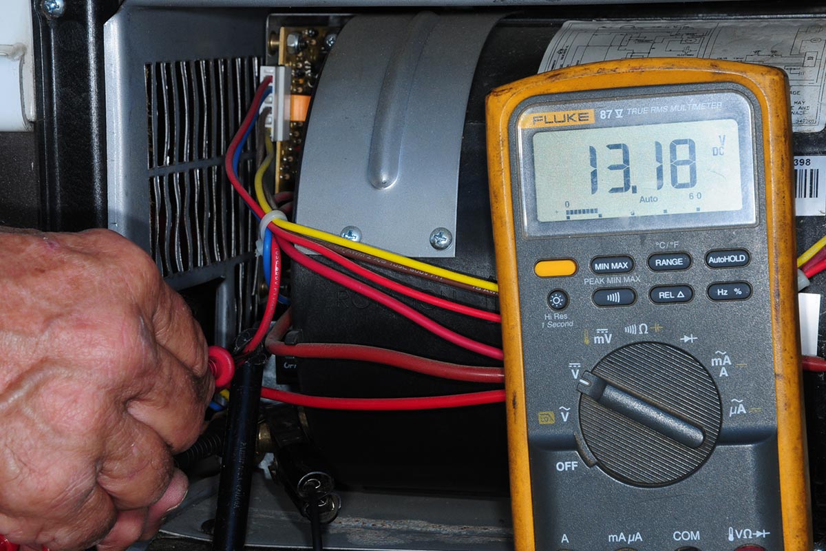
The obvious first check is for a blown fuse. If it’s good, make sure you have adequate voltage at the fuse and the furnace. Voltage can be verified using a multimeter and probes. There should be no less than 10.8 to 11 volts DC for the furnace to operate, but keep in mind that if voltage is that low, don’t expect the furnace to run very long. Nominal voltage with a fully charged battery should be more than 12 volts DC. At this point, you’ll need to evaluate whether the charging system — be it via the converter, inverter-charger or solar panels — is functioning properly.
Most furnaces will have an On/Off switch, which must have power across it. This switch is accessible via an outside door, but those furnaces without such access will have to be removed to check for power. If there is power at and through the switch, check the time delay relay, if so equipped. Replace as necessary after testing. While checking these components, be aware that a loose connection can also cause a no-start problem.
No. 4: Where’s the Air?
If the blower motor fails or is functioning erratically, the furnace will not ignite. The first step is to determine if there is adequate voltage to the furnace (see No. 3). If the motor sounds like it’s running too slowly, the brushes may be worn and not making proper contact on the motor windings. A mud dauber nest can also prevent the blower wheels from turning at top speed. Some furnaces may give you an audible hint that the motor is about to fail: If you hear squealing from inside the furnace upon start up, the chances are the motor is toast. If the blower motor tries to start and then stops, check the voltage at the blower motor. The circuit board determines that the fan is running and providing adequate air flow by using a sail switch, which closes when enough air hits the sail to activate the switch. These fail frequently; some RVers will carry extras in their toolbox, just in case. (See No. 7 for more.)
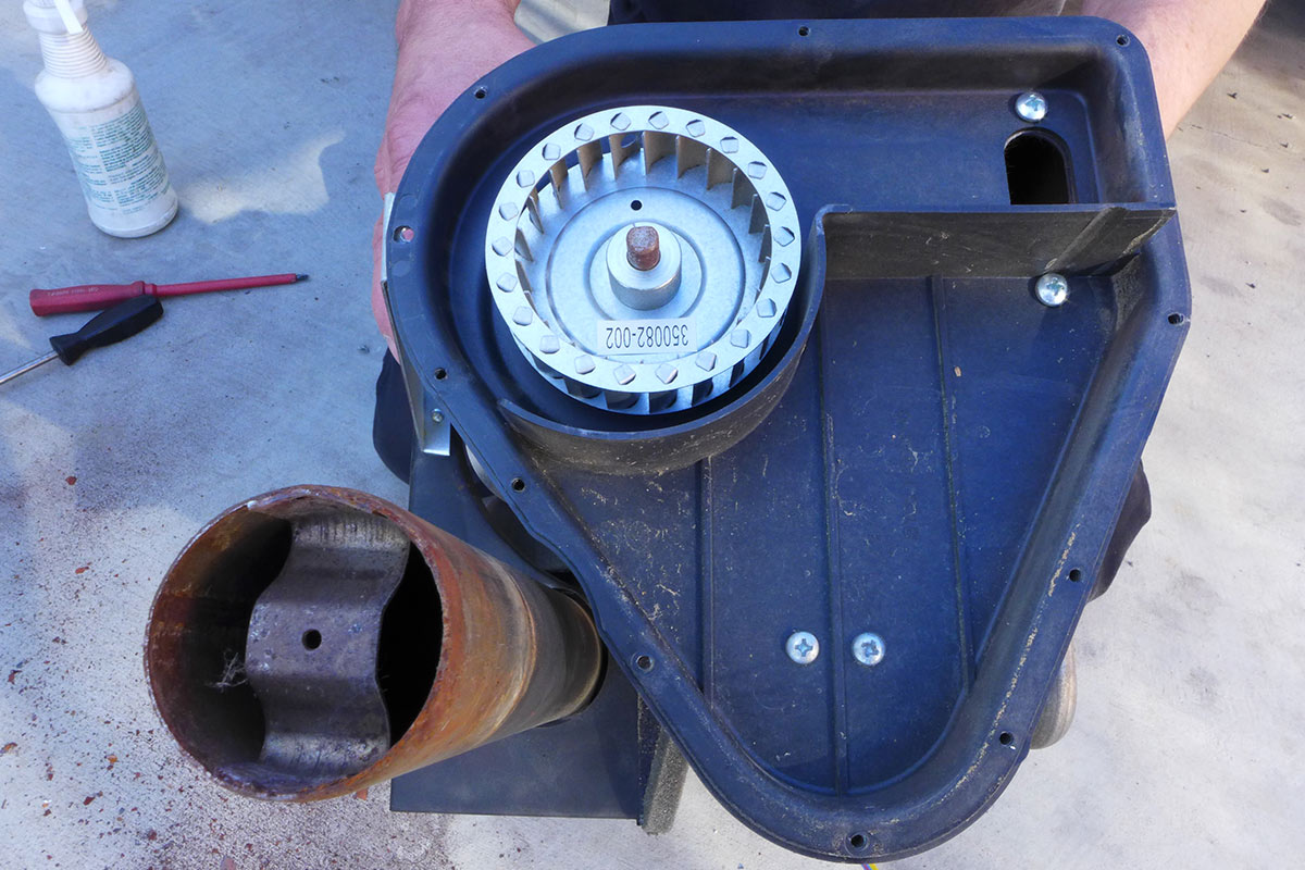
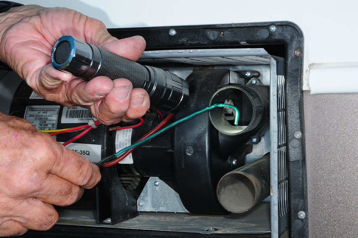
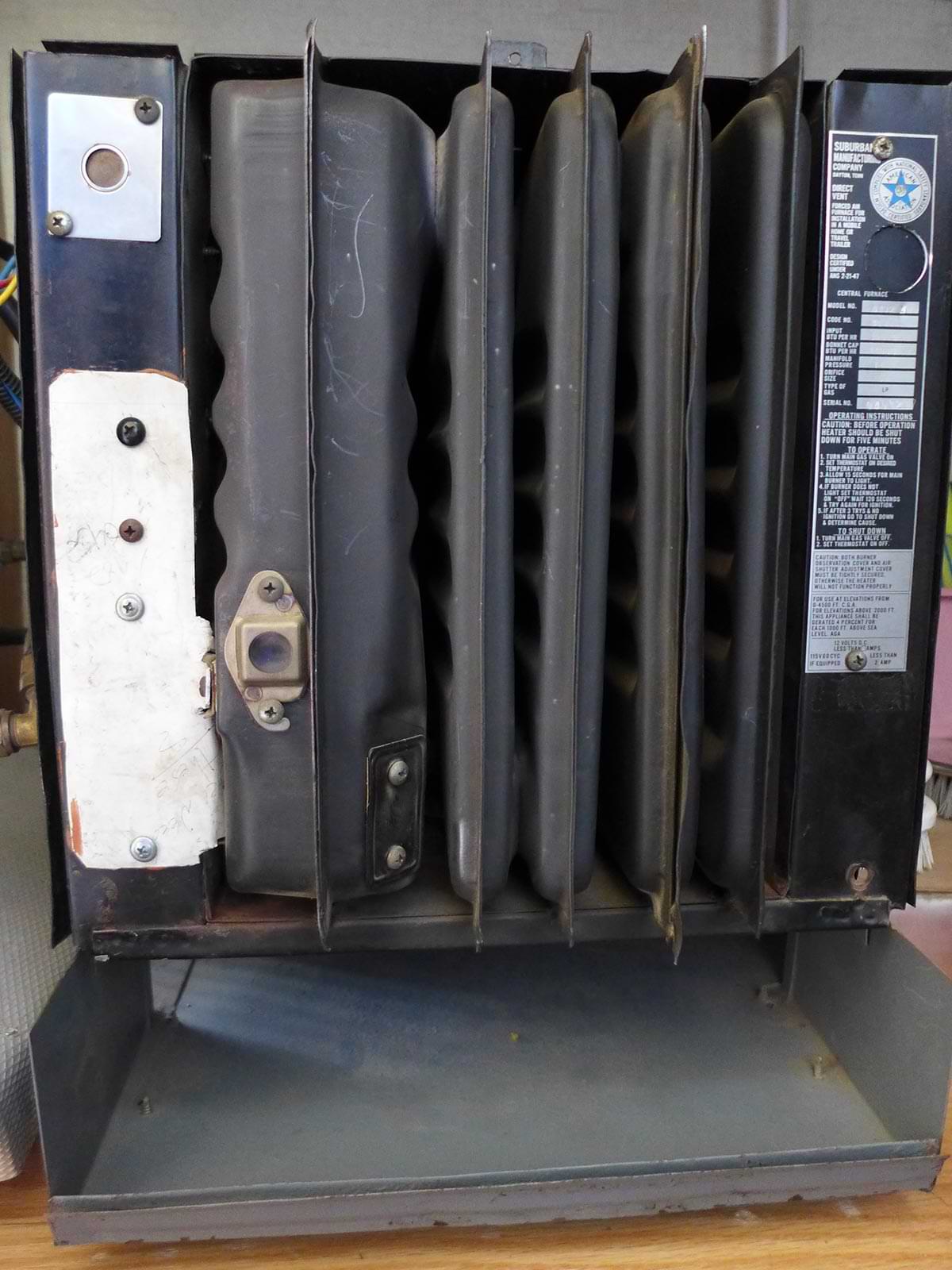
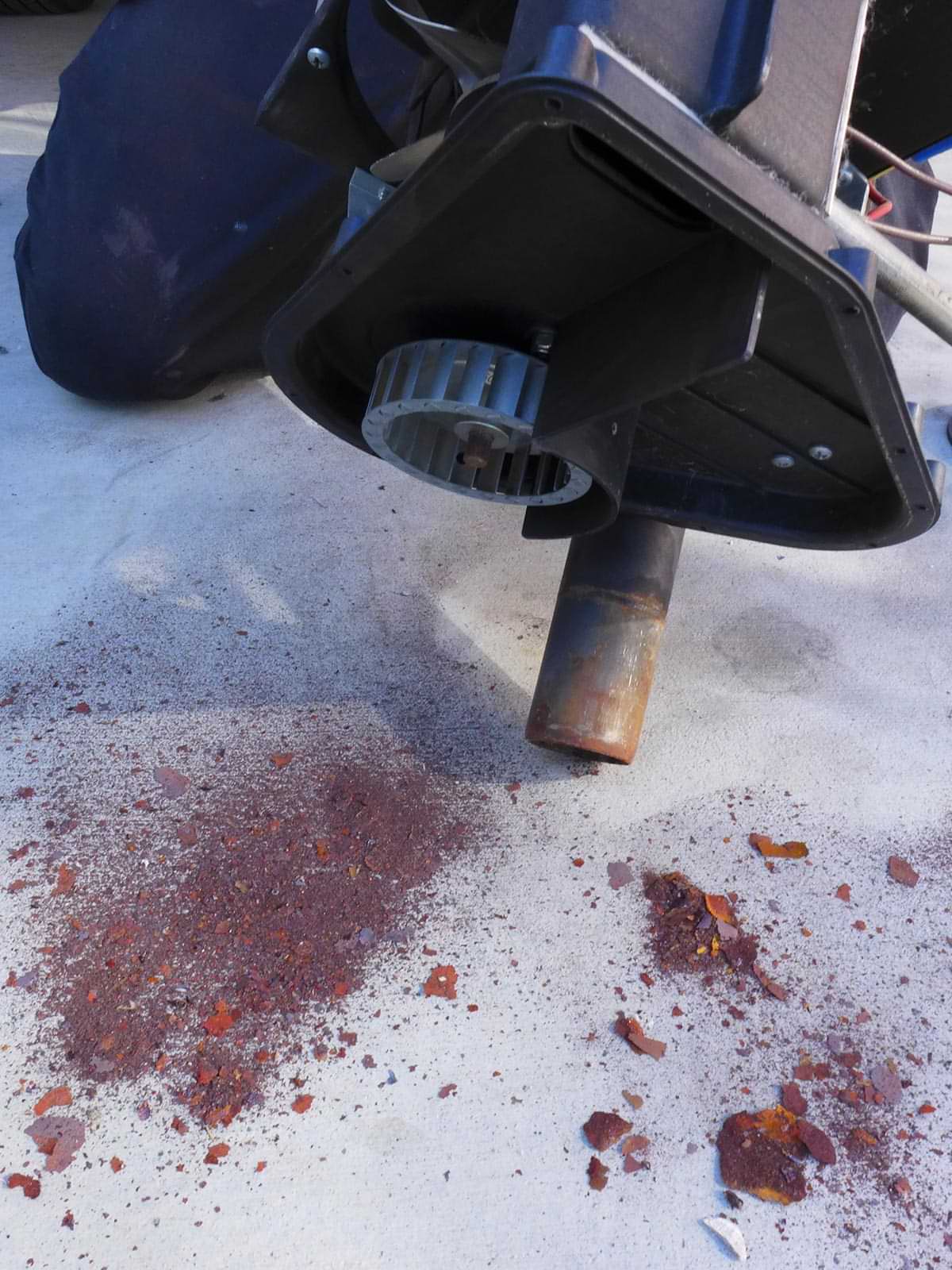
This image shows the typical configuration of an intake blower in a Suburban furnace. Not all intake blowers are accessible without removing the cover. Nests or other debris can create an improper air-fuel mixture.
No. 5: Keeping the Air Flowing
Blocking the return air vent and/or heat registers inside the RV is a no-no. Manufacturers require a certain amount of space (in square inches) around the return air vent and a certain number of heat registers to properly evacuate heat from the furnace.
Floor registers can collect an unbelievable amount of dirt over time — including pet hair, which can block the air flow through the ducting. If you have pets, consider removing the floor registers and applying a coarse screen material that will not impede the airflow but will keep pet hair and debris out of the ducting — and inspect/clean frequently. Some fifth wheels have a return air vent in the basement, which can be blocked by nearby stored items. Become familiar with the return air configuration and take measures to keep the vent clear at all times. If the return air vent is located in the galley, remove it and check periodically for anything that could have been dropped out of a drawer and possibly impede airflow.
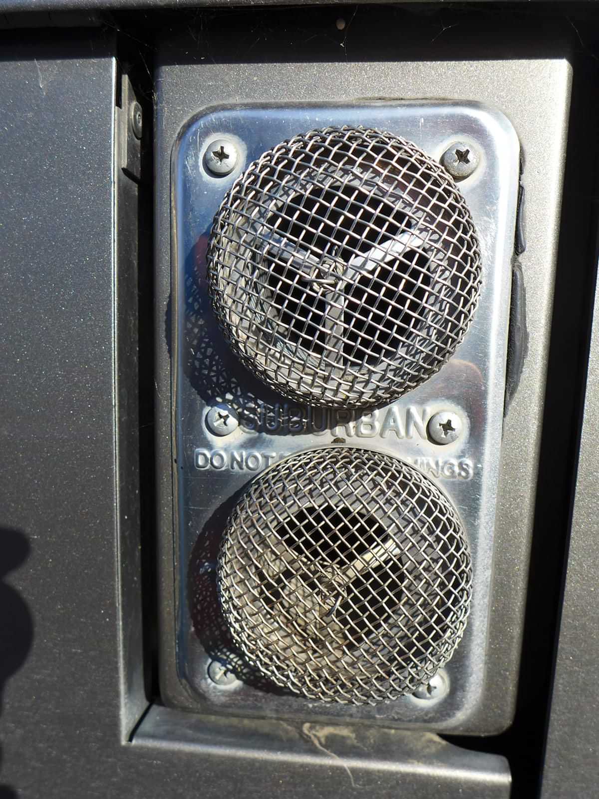
Although furnace manufacturers suggest otherwise, many owners cover the intake and exhaust ports with screens available in RV supply stores. These screens must be inspected frequently and cleaned of any obstructions to prevent furnace disfunction and overheating.
No. 6: Don’t Overlook the Thermostat
Most modern thermostats are very reliable, but a failure is not impossible. Diagnosing a thermostat problem requires that it be taken off the wall to inspect all the connections for integrity.
In the old days, wall thermostats were basic with an On-Off switch and a lever to set temperature. For these models, normally there are two blue wires coming from the furnace, which must be connected. Mechanical thermostats are still around but are not super accurate; owners learned to adjust the set points based on trial-and-error and interior comfort. If you suspect that the thermostat has failed, it can be removed from the wall and a jumper wire can be placed across the two terminals to test-activate the furnace. Keep in mind that every furnace has a fan-control board or time-delay relay and you will need to wait 20 or 30 seconds for it to start, and up to three minutes for the fan to shut off after the flame ceases.
Modern digital thermostats that control the air-conditioner(s) and the furnace are a bit more complicated. You can remove them to check for loose connections; testing is accomplished using an accurate voltmeter. In many cases, the blue furnace wire will go to the air-conditioner control board and not the thermostat.
Thermostats integrated into touch-screen control panels are more complicated and require testing by a trained technician, although many resets and testing can be accomplished right from the screen. Companies like Thor Industries, which includes a touch-screen panel to control systems in many of its RV lines, provide excellent support over the phone and online.
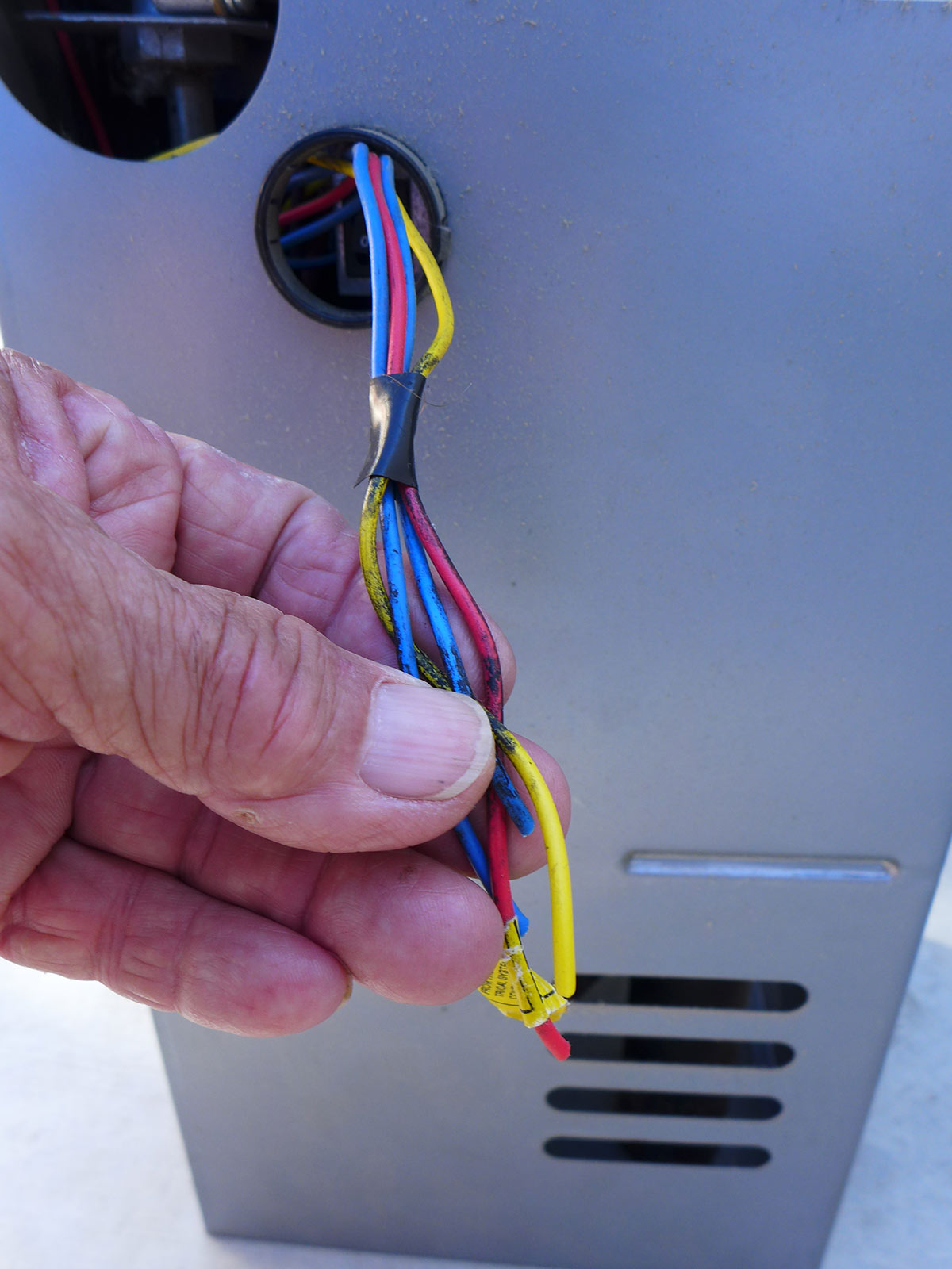
Don’t discount a failed thermostat when the furnace fails to function. In its simplest form, two (usually) blue wires control the furnace, and can be checked for continuity. More exotic thermostats that need attention will require the services of a trained technician. In this example, the two blue wires are for the thermostat, the red is the 12-volt DC positive wire and yellow wire is the ground — typical wiring schematic on most forced-air heating systems in RVs.
No. 7: Uncooperative Circuit Board
Depending on the age of your RV, the circuit board may or may not have an indicator light to let you know if it has failed. If the blower motor comes on and you hear no flame ignition, the circuit board and/or the sail switch is likely at fault.
Gaining access to the circuit board and sail switch is fairly easy on units with an outside access panel; units without this feature require complete removal. Test for voltage flowing through the sail switch to the circuit board if the indicator light on a circuit board is not lit. If you have an older-style PC board without an indicator light, you can test the voltage at the circuit board that comes from the sail switch or from the limit switch, depending on the model furnace. The limit switch is a thermal disc that will shut the furnace off when the burner heat exceeds set limits. The sail switch closes the circuit when the airflow from the fan is strong enough to move the flat portion on the switch arm. This is a safety device that will prevent flame ignition if there is not enough air moving through furnace. Should the combustion chamber overheat, the limit switch will shut down the power to the circuit board so that the flame goes out and allows the furnace to cool down. This usually only occurs when there’s a problem with venting (see No. 5). It’s fairly rare to find a limit switch that has failed.
Subsequent furnace models morphed to the use of a Fan 50 Plus circuit board, which was designed to eliminate the time-delay relay (see No. 10) and control the fan motor when there was a lack of ignition. Manufacturers transitioned to the current fan control circuit board, which is found on all furnaces today.
Most modern circuit boards can be tested with a tool utilized by RV dealerships and repair centers. You may be able to take the board to a local shop and ask if its technicians will test it. The best replacement circuit boards are made by Dinosaur Electronics (dinosaurelectronics.com).
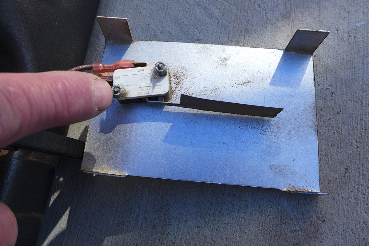
The limit switch (models will vary) prevents the combustion chamber from overheating to the point where safety could be compromised. This is one of the checkpoints for tracing voltage to the circuit board or the sail switch.
No. 8: The Right Flame
Soot appearing on and around the furnace vent indicates that there’s an issue with the air/fuel mixture. Proper ignition is affected by LP-gas pressure, air intake/discharge integrity, mud dauber nests or debris in the burner tube. This is usually indicated by a flame that is yellow and dancing around the top of the burner. Once the soot shows up, it will only get worse until the problem is solved.
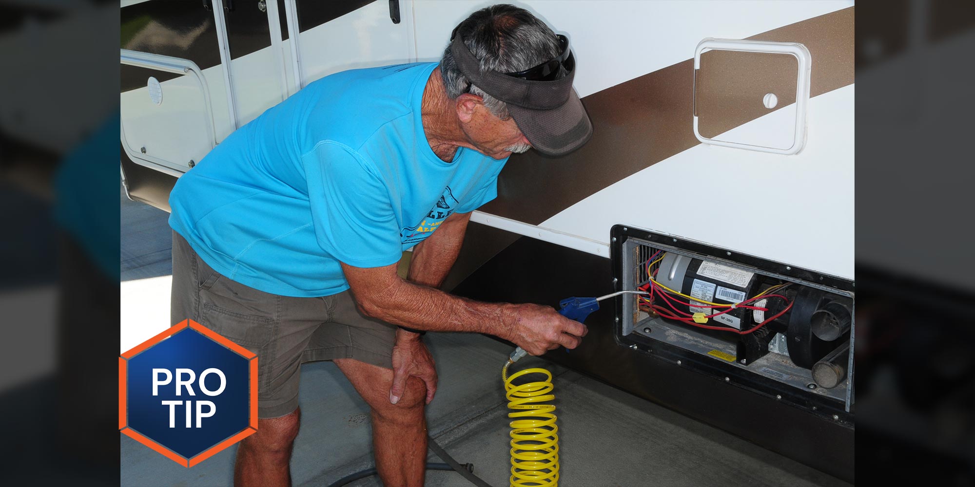
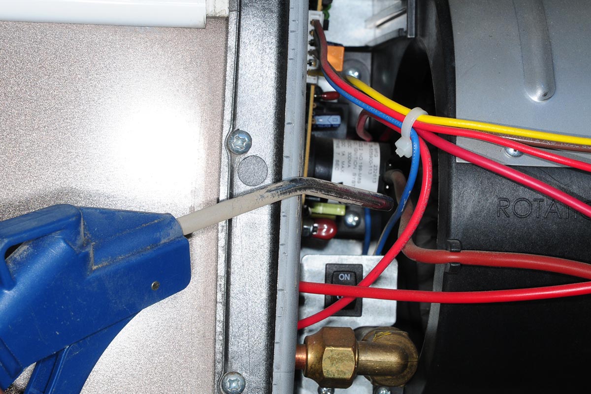
Remove the furnace and find a suitable bench or location to clean all the parts in the combustion chamber. Cleaning soot from the furnace will require a large volume of air pressure, not to exceed 200 PSI. The tricky part is removing the burner from the furnace for cleaning. Keep in mind that rust can be an issue with some older burners, closing the slots (in the burner) over a period of time and causing an improper flame. Blow air through the intake and discharge vents and through the front of the furnace after removing the electrode assembly to gain access to the combustion chamber. This is very messy, and black dust will go everywhere; wear a mask.
Extreme cases of improper ignition can be traced to the burner orifice; seek professional help if you are not familiar with this procedure. Another cause of improper ignition can be LP-gas pressure (see No. 1). Use caution when working with combustion systems; it can be very dangerous.
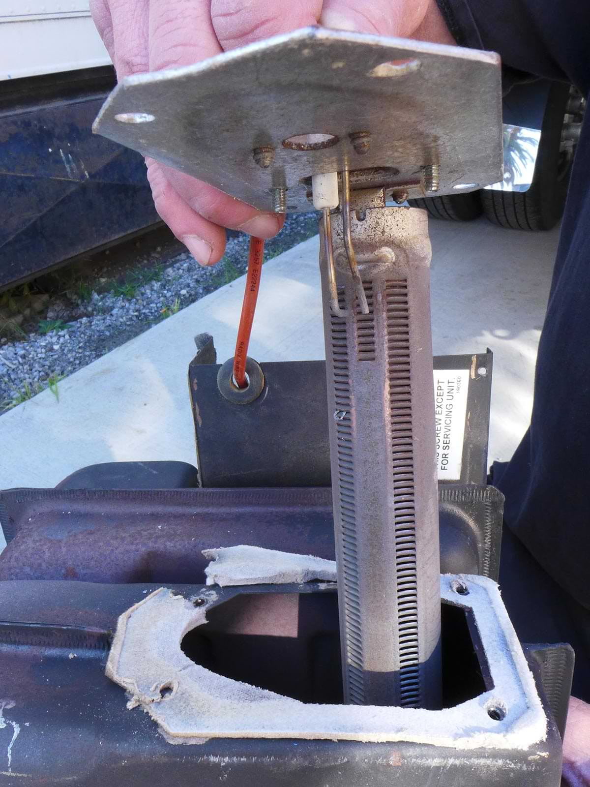
It’s not uncommon for rust to build up over the years in a forced-air furnace. Rust is created by condensation caused by intense heating through combustion and cool down. Rust building up over time will affect the air-fuel mixture, leading to an erratic flame—and in some cases, no flame.
No. 9: Loosey Goosey
With all the vibration and movement RVs endure while on the highway — and wires running everywhere — it’s not uncommon to find a loose connection or a wire that has been compromised. Loose connections can be found just about anywhere, from the fuse panel to the furnace itself. Sometimes bad connections are obvious, but more often you’ll need to use a voltmeter to identify the culprit. One overlooked item is the ignition wire from the electrode to the circuit board. Built-up corrosion or a loose terminal can create enough resistance to cause ignition failure. If you suspect a loose connection, you will need to check the 12-volt DC, thermostat and internal wiring.
Electrodes used in all direct-spark-ignition forced-air furnaces can become inoperative if the gap is not correct (specs are provided for all furnaces). The gap between the ground and the electrode is somewhat critical, as well as the gap between the electrode and the top of the burner. When inspecting an electrode, be sure that the slots are clear of rust and debris below the electrode assembly for proper spark and ignition.
No 10: Patience, My Friend
Older model furnaces use a time-delay relay, which delays the blower wheel from coming on — and, most importantly, allows the combustion chamber to cool down before shutting down the furnace. This is important because of the intense heat in the combustion chamber; repeated shutdowns without cooling the combustion chamber would ultimately lead to furnace failure.
Normally, a defective time-delay relay will not allow the furnace blower motor to come on. There are instances when the blower motor will cycle several times before remaining off or on. The time-delay relay functions by sensing voltage via a signal from the thermostat. If you suspect the time-delay relay is defective, use a voltmeter to check power coming into the relay and to the thermostat side of the relay. If it has power at both terminals, then the relay could be defective, providing you already confirmed that the ground to the relay is adequate. The ground on the relay is usually a short wire running to a ground block and can be checked visually. When replacing the time delay relay, be sure that you get the proper one for the particular furnace; they are not interchangeable.
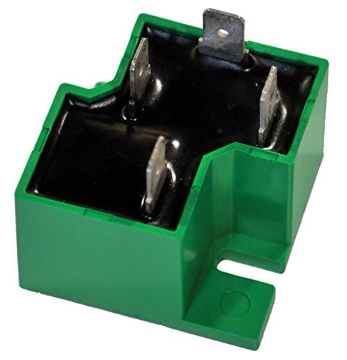
The time-delay relay was used in older furnaces before the advent of fan-control circuit boards. If it’s defective, the blower motor will not run. If the blower motor cycles before remaining on, suspect a failing time-delay relay. Shown is a replacement time-delay relay from Dinosaur Electronics sold on Amazon.
Already a Subscriber? Click here for Access to the Full Issues.