Drawing to a Close - RV Enthusiast Magazine

Drawing to a Close

by | Jan 27, 2022 | Accessories, Electrical, Repairs and Upkeep

When routing the wires, make sure the bend is identical to the existing cable so that it will flex properly as the awning opens and retracts.

Photos by the author

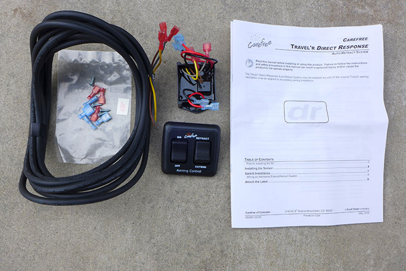
Carefree of Colorado’s Direct Response upgrade kit for Traveler or Eclipse awnings will automatically retract an awning before the winds have their way with the fabric

An extended patio awning is a wonderful thing to have when you’re camping; one that’s ravaged by the wind is not. Strong, unpredictable winds can literally destroy your patio awning in a matter of seconds. Extreme weather is probably the Number One reason patio awnings are ruined, which likely also results in collateral damage to the RV, not to mention impacting your entire vacation. If you happen to be in the RV at the time of a wind event you can quickly retract the awning, but if you forget to retract it before leaving the site for a while, you have two choices: hope for the best in the event of an unexpected storm — or rely on an automatic closure system that retracts the awning at the first sign of trouble. We prefer the latter.

Carefree of Colorado, a leading manufacturer of RV awnings, offers a solution to this dilemma with its Direct Response electronic motion sensor upgrade, which will automatically retract the awning in strong winds. The device mounts in the vicinity of the motor/head assembly and has a preset sensitivity, which can be turned on or off when washing the awning fabric. The first hint of strong winds or a sudden gust will signal the system to retract the fabric. Many awnings are fitted with such a device, but it is typically reserved for more expensive RVs; most older rigs aren’t equipped with an automatic retraction system. The kit for the Carefree Traveler, part number SR0093, retails around $98, while the kit for the Eclipse model (SR0036) is $350. Most handy owners are capable of installing either kit.

the kit laid out
the wires on display
The kit comes complete with everything needed to install the Direct Response, except for the wire needed to connect power to the on/off switch. Wiring for power will require 14-gauge primary wire, which is available in hardware and auto parts stores and online. Black and red wire was used for this project.

Installation

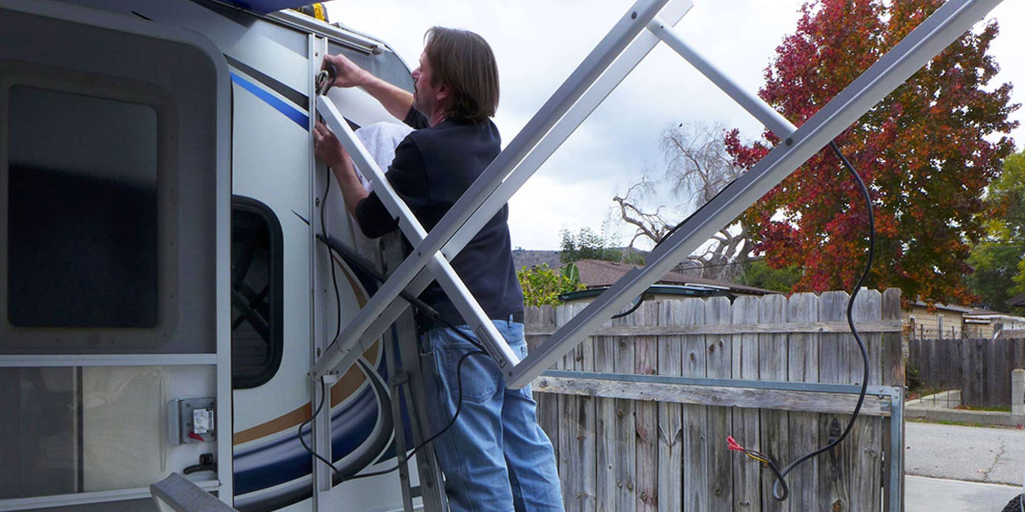
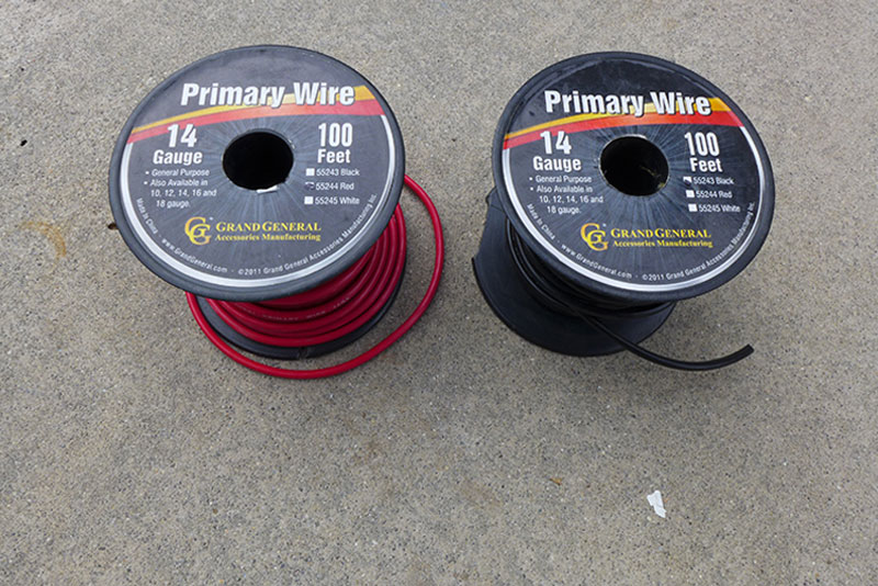
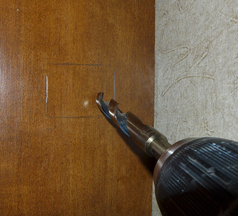
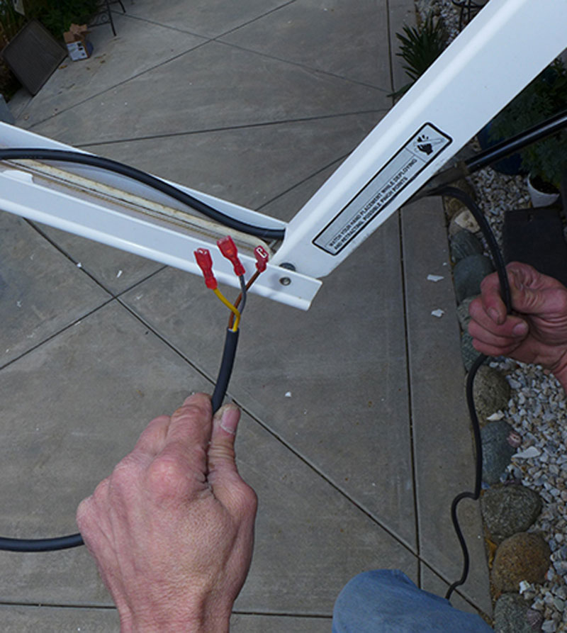
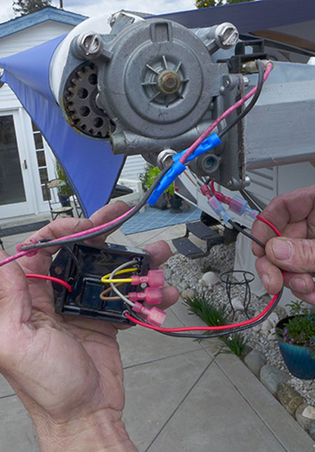
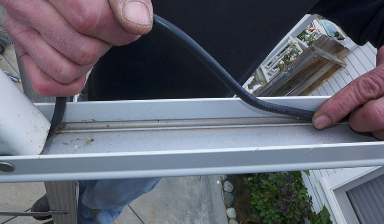
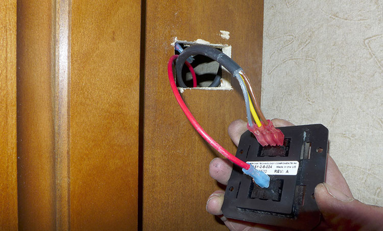
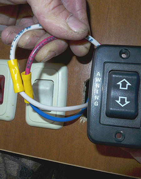
Access to the front motor/head assembly will be necessary to complete the installation, which should take just a couple of hours. You’ll have to route new wiring to the awning sensor — but before you get to that step, you’ll need to disconnect the power from the original switch after fully extending the awning. The original “extend and retract” switch will not be functional after the Direct Response is installed. It will be necessary to find a find a suitable location (in a closet or cupboard or on a wall) to mount the new switch assembly where a suitable 12-volt DC power supply is nearby — either from the original switch (like it was done for this project), a reading light or any other 12-volt DC source in the area. The wire for this step is not provided with the kit, so plan on procuring about 20 feet of 14-gauge stranded wire in red and black to have on hand. This circuit also needs to be protected by a 15-amp fuse.

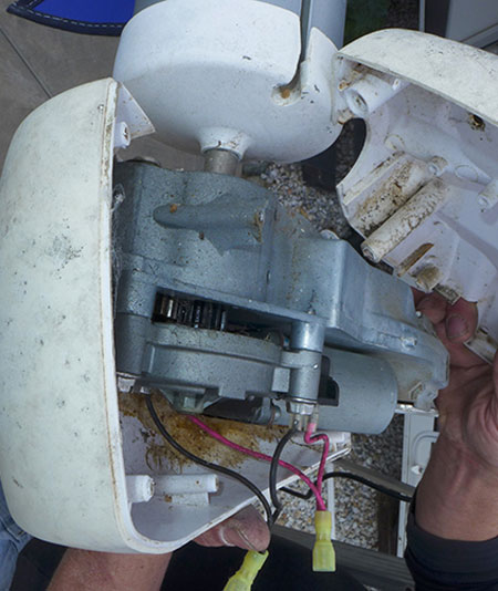
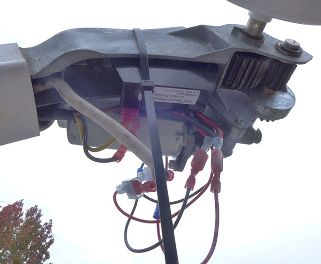
Once you establish a mounting location for the new switch assembly, you’ll need to follow the directions to complete the process, which are very explicit and supported by a wiring schematic. The sensor module will be mounted near the motor assembly, which is located under the front head cover (on the right side while looking at the awning).

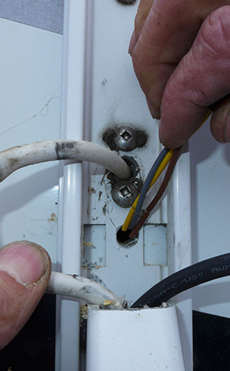
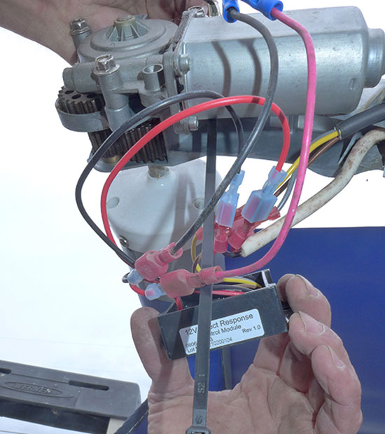
Everything for this installation went pretty smoothly, although it was a little tricky pressing the wiring harness into the hardware assembly slot specifically allocated for this purpose. It was also difficult to understand exactly where the company wanted the sensor module to go; we put it into the slot that made the most sense and secured it with cable ties rather than the double-sided tape that was supposed to be in the kit (but wasn’t). That diversion turned out to be best, since double-sided tape has a tendency to loosen with age and exposure to heat and you don’t want the sensor unit flopping around inside the plastic cover that surrounds the motor assembly.

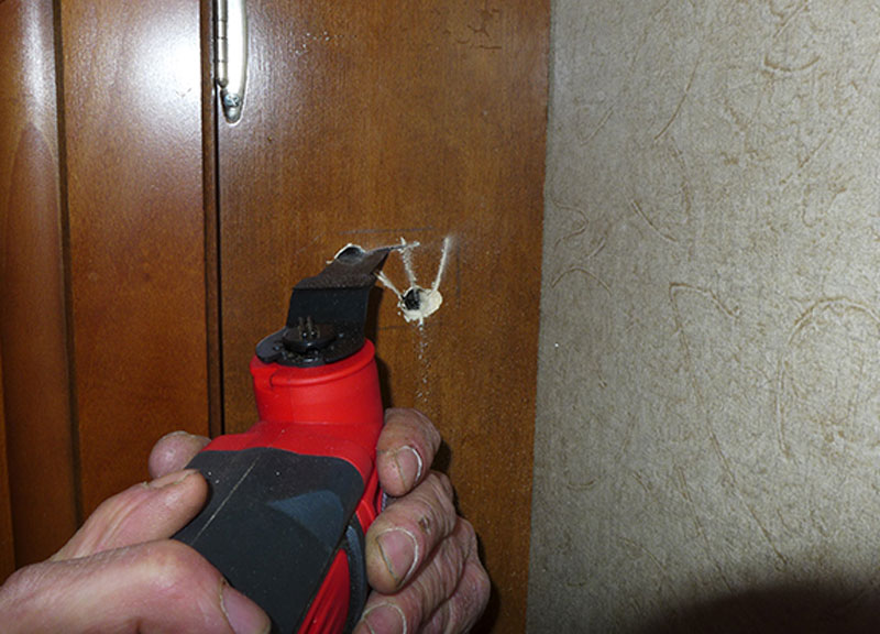
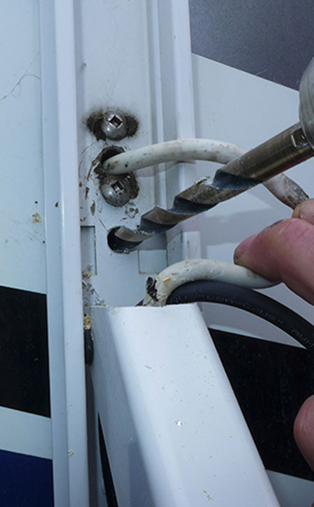
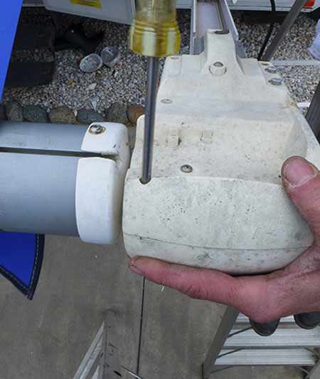
A second stumbling block was experienced when trying to remove the plastic cover. In this case, a couple of the screws were rusted and needed to be drilled out to free the cover. All rusted screws should be replaced — in any project. Also, there are a few safety standards that must be considered and are clearly outlined in the instructions.

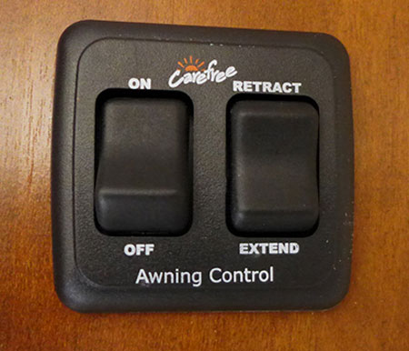
Once the installation was finished, the mechanism was tested a number of times by simulating a wind event by bouncing the end of the awning with the bristle end of a broom. The system worked perfectly every time, offering a strong sense of security and comfort knowing that the awning and/or the RV won’t be damaged and it won’t be necessary to initiate an insurance claim. Obviously, the switch must be in the “ON” position at all times to put the system on standby.

Of course, while Direct Response keeps the awning safe from weather events, most experienced owners will still retract the awning when they are away from the RV. There’s no sense in allowing the awning to flop around in the wind before it hits the threshold that automatically retracts the fabric. When you forget, however, it’s nice to know you’re still protected.

seeing the drawn out area
After finding a suitable location for the switch assembly, mark the cutout with a pencil and drill pilot holes in each corner.
using a cordless oscillating tool
A cordless oscillating tool was used to make the cutout (a small jab saw will also work). Just be careful not to scar the adjoining woodwork.
looking at the wiring harness
The wiring harness in the kit is installed in a specific channel in the awning hard- ware. The cable must be pushed firmly into the channel so it will stay in position without getting pinched while the arm is in motion.
drilling the holes
threading the wires through the holes
A 7/16-inch hole is drilled through the hardware just below the existing cable into the cupboard where the switch assembly is mounted. It’s a little tricky to get the wires through the 7/16-inch hole. To accomplish this, it’s best to feed one wire at a time through the hole.
removing the end cap
Remove the end cap from the hardware to expose the motor and gear box assembly. Access is on the front of the awning. Two of the screws were rusted and required drilling to remove. Always replace any rusted screws.
seeing the gear box open
The inner cap will have to be removed to pull the red and black wires off the emergency terminals. These terminals will not be used with the Direct Response unit; doing so will fry the motion sensor module.
looking at the motor and leads
The motor leads were installed following the diagram in the installation instructions. The connectors were cut from the red and black wires that originally were removed from the emergency terminals and butt-connected to the motor leads for a more permanent installation.
adding the cable tie
The instructions show where the module must be placed, but they are not very clear, so we found ourselves also relying on common sense. There was supposed to be double-sided tape on the module for mounting, but it was not included. However, we realized that cable ties will work better, so we added them.
looking at the assembly
With the cover removed for installation of the module, take time to inspect the gears. This is also a great time to lubricate the gears with white lithium grease. Once everything checks out and the module is in place, put the covers back on.
the cable being placed
After the module was installed, the final 3-4 feet of cable were routed in the awning arm channel provided for this purpose.
attaching the wiring to the right terminals
Following the instructions, the wiring to the appropriate terminals was installed in the back of the switch assembly.
dislocating the old switch
The wiring from the original extend/retract switch was disconnected to prevent accidental activation. Although the switch will be put back in the original location, it’s only there to keep from patching a hole in the wood; wires are not re-connected.
the new switch
Once the installation is completed, extend and retract the awning three or four times to make sure everything is working correctly and no wires are pinched. With the awning extended, use the bristle end of a broom to agitate the awning near the sensor to confirm that the module is working and the awning is closing. When the awning is extended, be sure to leave the switch in the ON position, otherwise it won’t retract automatically.
Sources:

Carefree of Colorado
303-469-3324
carefreeofcolorado.com

Get Updates
Subscribe today and never miss an issue!
Get all the latest tips and news to keep you moving on that open road!
RV Enthusiast January/March 2024 Issue
Current Issue
January/March 2024
Spring is back in bloom and with it we are proud to present our latest issue of RV Enthusiast! The January/March issue covers furnace failures and how to fix them, the best batteries for boondocking, quick and easy weekend projects, PLUS so much more!

Already a Subscriber? Click here for Access to the Full Issues.

Share This