Down the Drain
Photos by the author
Cable-actuated dump valves get a bad rap for operational difficulties, which can be mitigated with the right products from Valterra and proper installation.
In most cases, anyway.
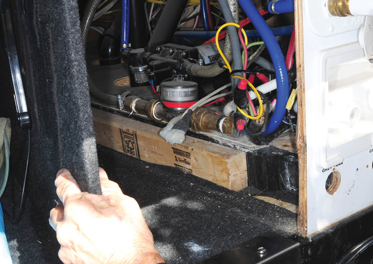
Many valves are attached near the outlet pipe and readily accessible, while some are operated from a remote location using cables or switches for electric systems. When the cables break or the valves stick, you’ll have to tear into the bowels of the underbelly to make the repairs or replacement.
Early on, I installed electric valves on my fifth wheel to offset the poor performance of the cheap cables (necessary for pulling and pushing the internal blades and installed by the factory) that were attached by simply bending the internal wire over a loop connected to the knife-blade valve — a cheesy, unreliable set-up at best. Within days of ownership, these valves were replaced with electric counterparts. It was a nice concept, but after multiple failures it was time to go back to a manual operation.
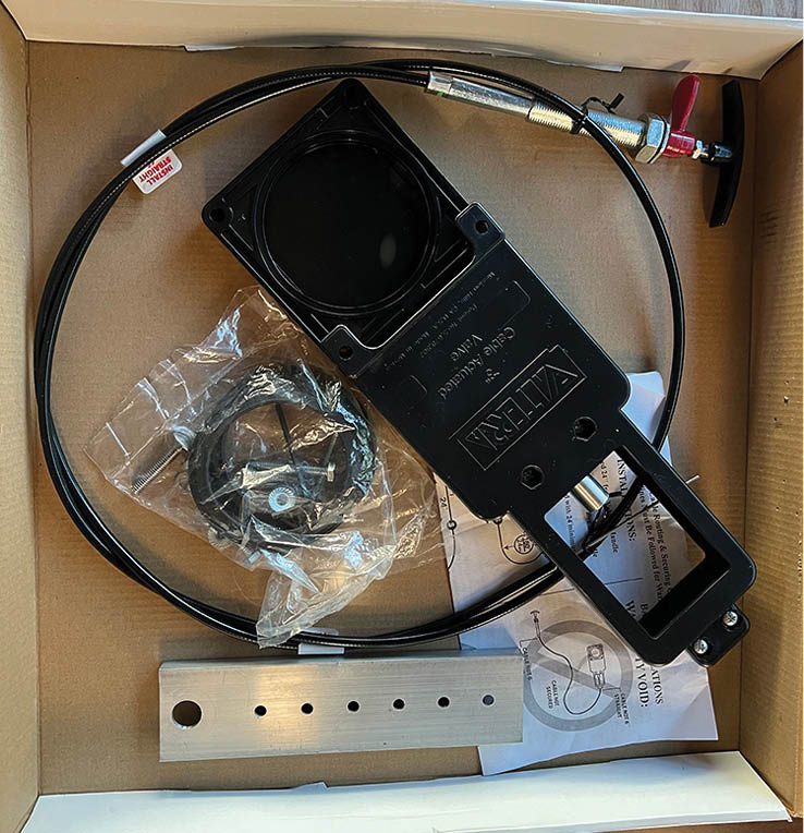
The replacement parts of choice were the Valterra.com TC372, 3-inch cable actuated valves. Most owners will also likely need the company’s TC172 1 ½-inch valve for the gray water tank. For this project, however, the gray-water valve was adapted to handle a 3-inch electric valve, so the 1 ½-inch configuration was no longer in play. Three Valterra TC372 kits were ordered from Amazon at $59.66 each. (Interestingly, the smaller 1 ½-inch valve kit sells for $67.07. Go figure.)
If the original cables are still in place, they can be used to snake through the new ones. Basically, the cables do not like lots of tight bends, which will prevent them from moving freely. In this case, we found a good compromise for routing the cables and the internal wires moved with minimum resistance. Fortunately, the internal stainless-steel wire is wrapped by a decent-quality cable housing, which promotes free movement without hang-ups.
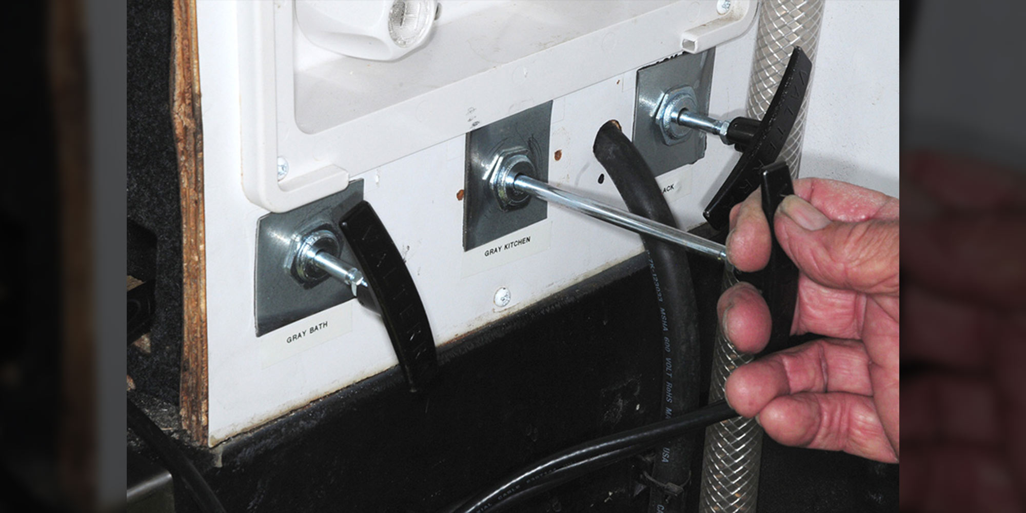
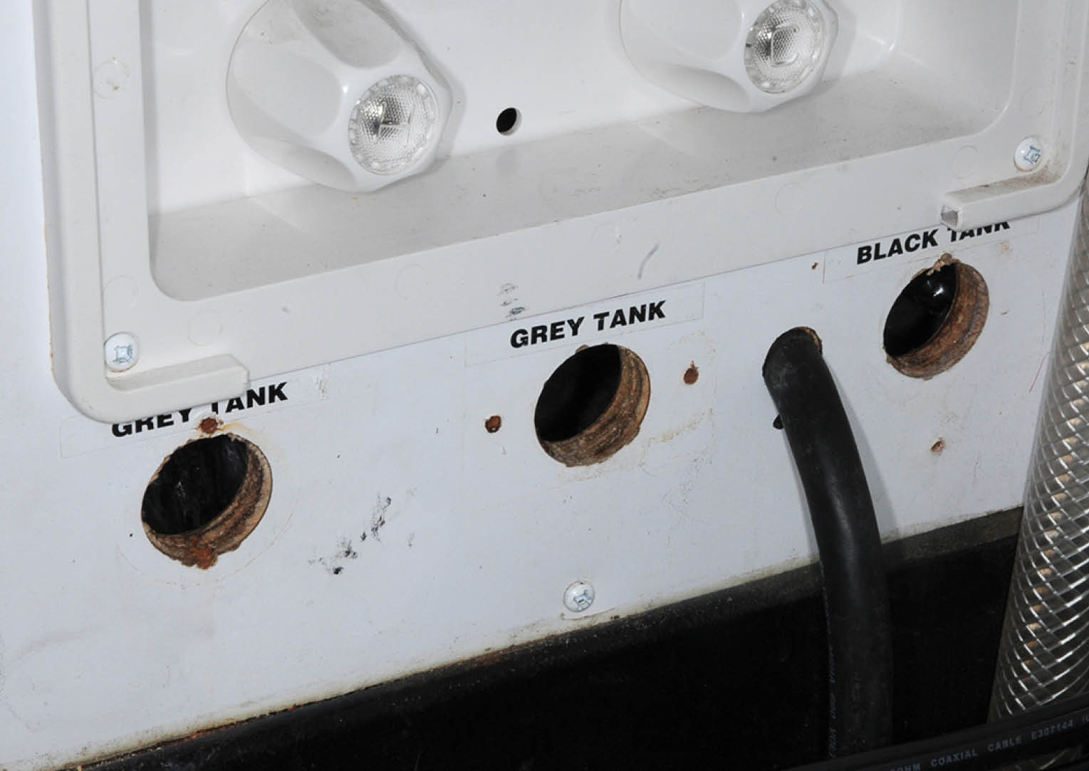
Originally, the three factory cables were mounted in the utility compartment; over the years, the holes in the wall were further modified for switches and a 12-volt DC power outlet. All these components were stripped from the wall and the holes covered with galvanized sheet metal plates that were “stuck” on with 3M VHB two-face tape. Once the plates were in place — and the VHB tape sticks like crazy — 5/8-inch holes were drilled to accommodate the new cable assemblies. Alternatively, each kit came with an aluminum plate with holes that can be mounted to a convenient outside surface (think frame) where the cables can be routed from. No doubt, that would have made the cable routing easier in this fifth wheel, but we preferred the cables be locked up inside the utility compartment.
As you might surmise, the real “fun” began after the cables were routed. First, the tanks were drained into the sewer and the black tank rinsed thoroughly and left open for a while to allow any “stragglers” to find their way out and promote some drying. Keep in mind that you’re still not home-free and it’s best to wear disposable gloves, dirty work clothes, eye protection and a mask during the process of removing the old valves — and keep a bucket handy and your mouth closed.
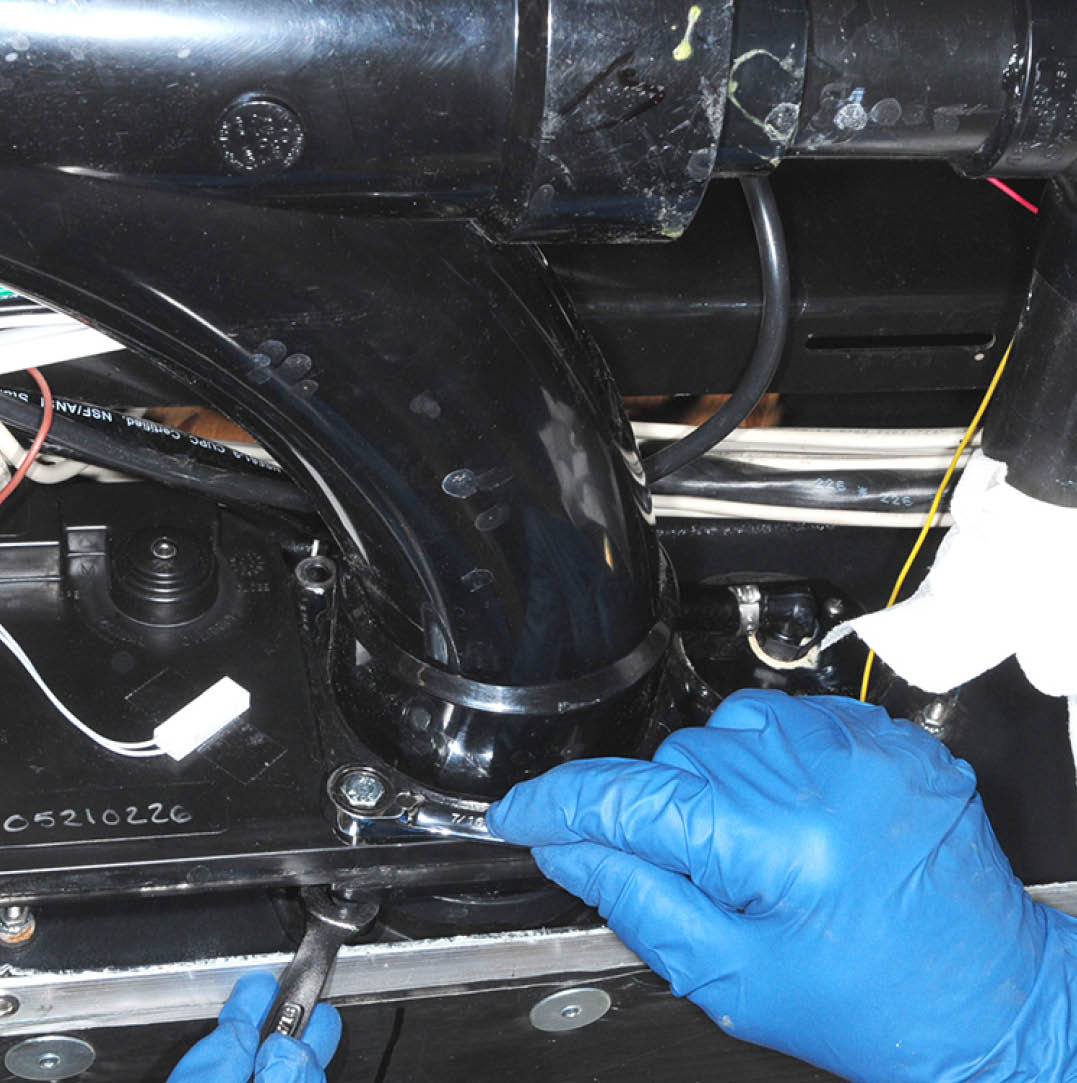
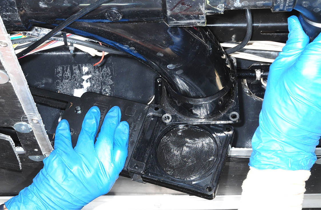
Working on your back is, of course, not optimal, but there’s no other choice. Earlier, cutouts with removable covers were configured in the belly pan to access the dump valves, which sped up the process. If this is your first time working on the valves, the belly pan will have to be dropped, which is not entertaining when all the construction shrapnel comes raining down on your body.
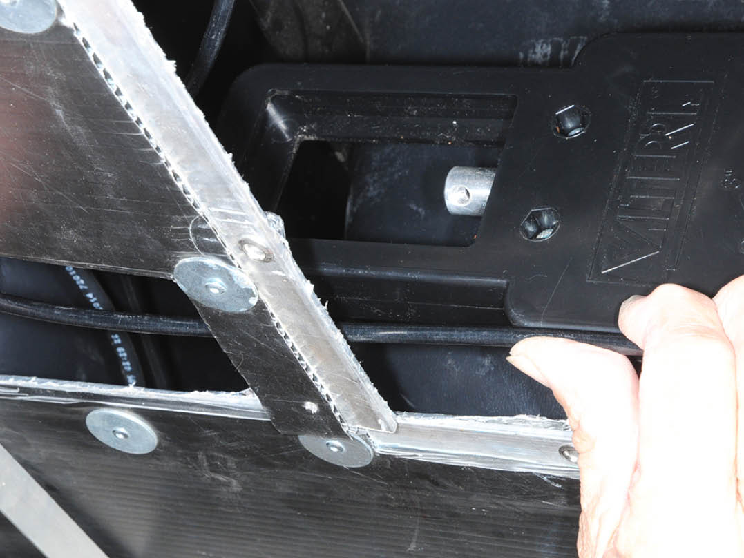
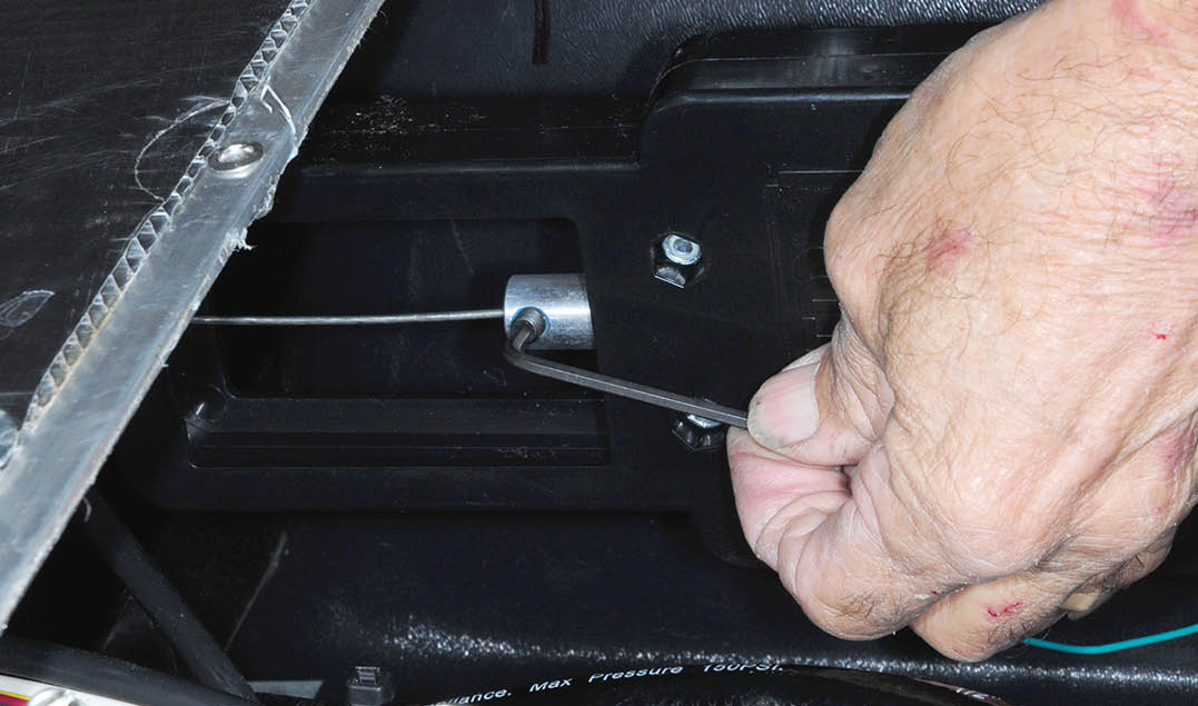
Removing the existing dump valves was an easy task since there are only four bolts to contend with. More than likely, it will take some calisthenics to reach a few of the bolts, but the process should only take a few minutes and maybe a scraped knuckle. After cleaning up the area, the new valves were bolted into place, taking care to locate the new seals over the existing flanges. Do not overtighten the bolts.
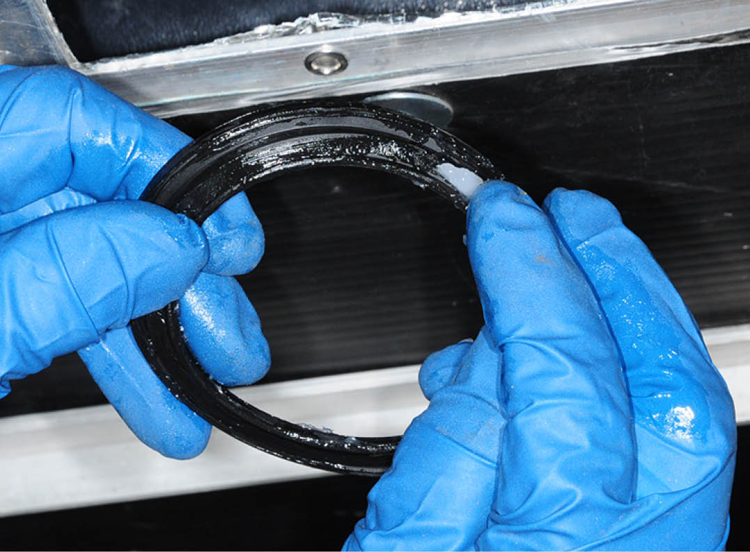
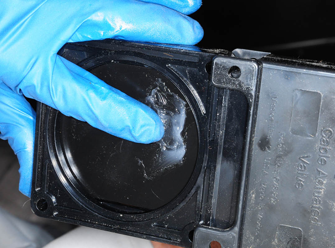
There are couple of housekeeping chores before mounting the new valves. Make sure the new seals are coated with a thin layer of plumber’s grease, which will help prevent leaks and keep them in place when mounting the new valves. It’s also necessary to grease the knife blade on both sides; just add enough to cover the surface with a thin layer. Adding the grease will allow the cables to push and pull the blades freely, which is critical for long-term trouble-free service.
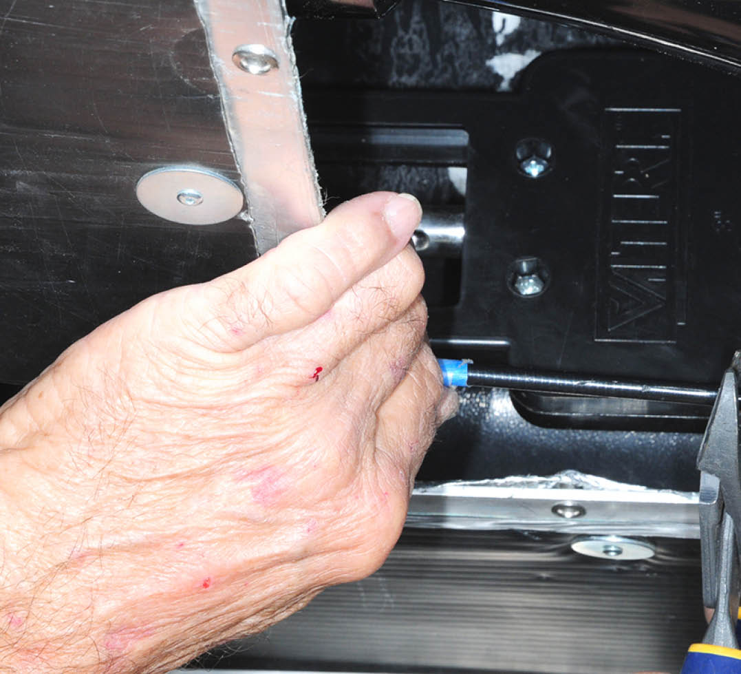
Before mounting the valves, make sure the cable wires will fit into the coupler. We learned that the hard way when one of the couplers was not reamed out properly and the wire didn’t fit. We did not want to remove the valve body, so we struggled to drill out the coupler, which turned out to be a nightmare — Rube Goldberg would be proud of our convoluted effort. Gehr held a drill bit with a locking pliers while I turned the coupler with a long nose pliers. It finally worked but prompted this tip to prevent problems for others. Also, the Allen set screw was missing from all three kits, which required a trip to the hardware store to purchase replacements with ¼-20 threads.
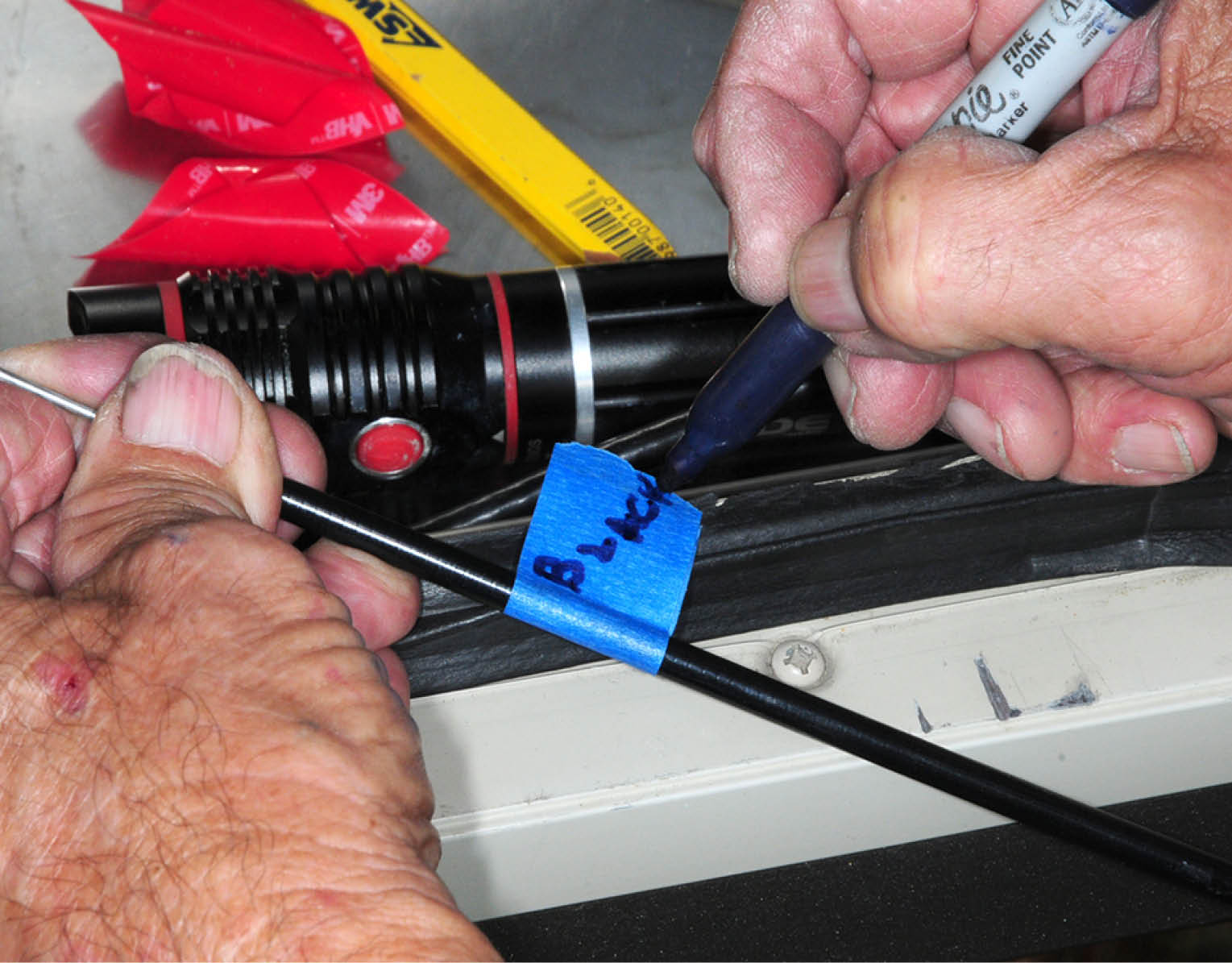
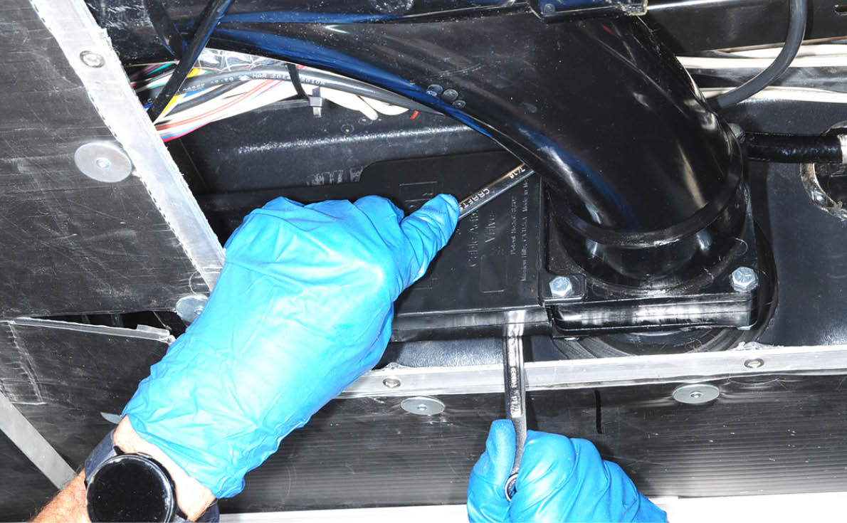
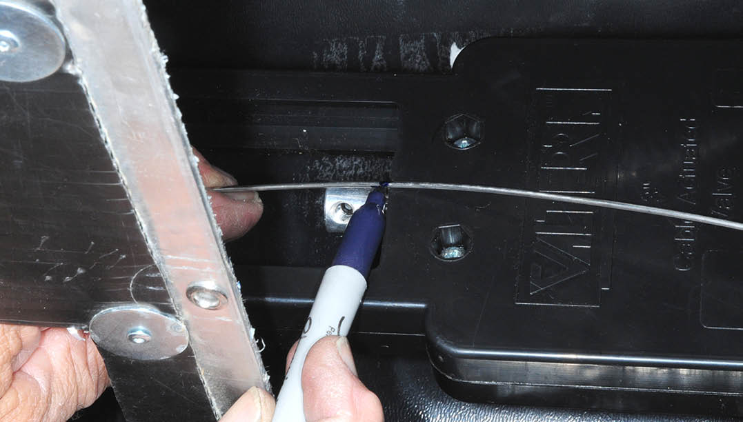
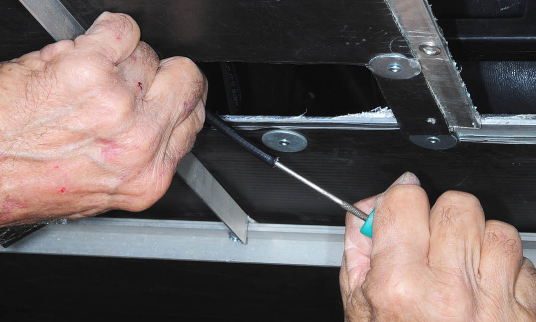
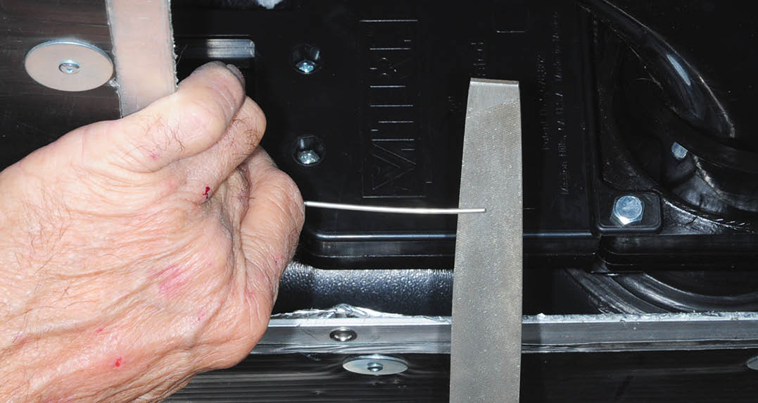
The last step was to install the cables into the valve bodies. Before continuing, we confirmed that the red tab was in place between the utility wall and the cable handle to facilitate proper length; it was removed when the job was finished. Likely, there will be more cable than needed. After verifying the routing would work, the internal wire was pulled out and the cable casing was cut to fit through the collar entry hole (which is the strain relief). Once the basic length is determined, the wire is cut — leaving 4 3/8 inches from the end of the cable casing so that it can be threaded into the coupler. It’s best to use a cable cutter; regular wire cutters will likely bend the casing (and even the wire) and restrict movement. Smoothing out the end of the casing with a round file will remove any burrs or sharp edges that can hang up the wire.
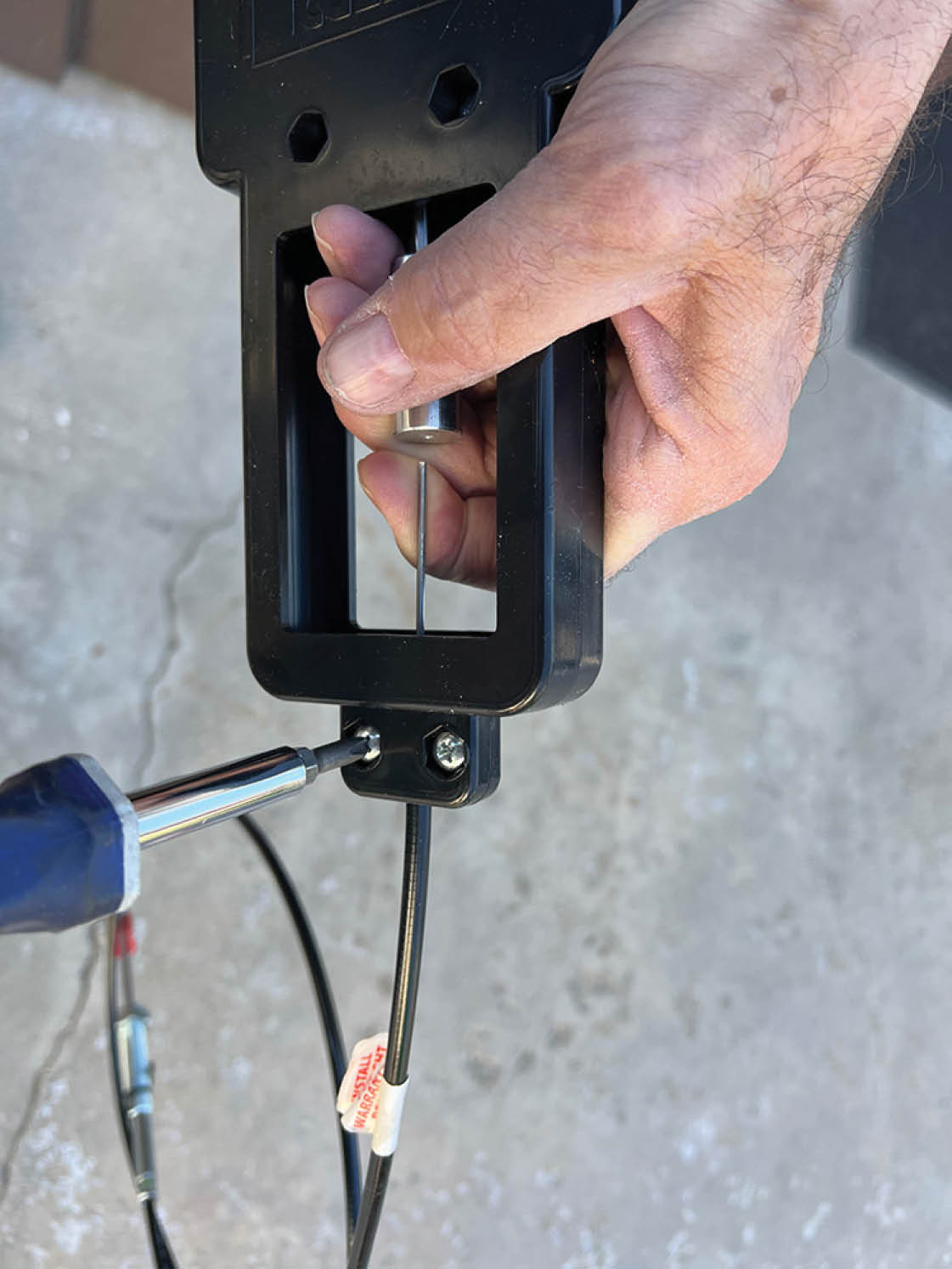
Once the cable was cut to length, the wire was secured in the coupler by tightening the set screw after coating with a thread locker like blue Loctite (do not use red) and the cable was locked into the collar in the valve housing. Finally, the cable was secured with zip ties to prevent dangling, which will impact smooth operation of the valves.
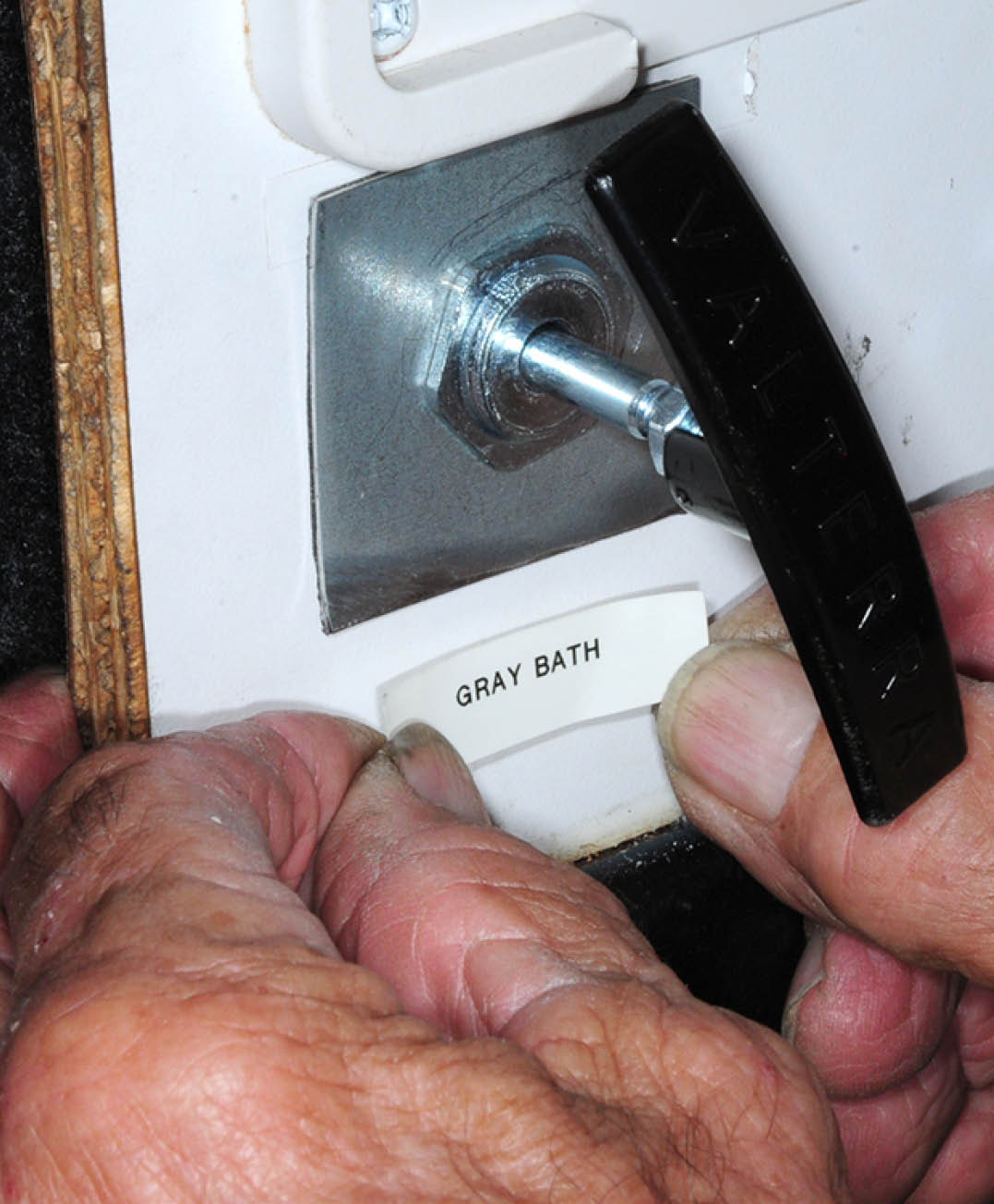
While not a necessity, we also printed labels and placed them under each cable handle to identify the holding tanks; each handle was pulled and closed multiple times to confirm smooth operation. It’s best to add water to each tank to make sure there are no leaks before buttoning up the belly pan or access panels. In this case, one valve leaked and the offending bolts were tightened until the leak stopped. Again, do not overtighten the nuts and bolts or the valves will stick and even fail to move fully when pulling or pushing the internal wire.
After four months of full-time operation, all the cables are working smoothly — something appreciated by all owners when dealing with holding tanks.
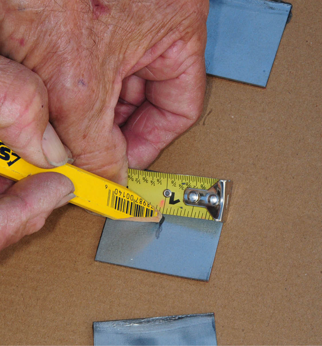
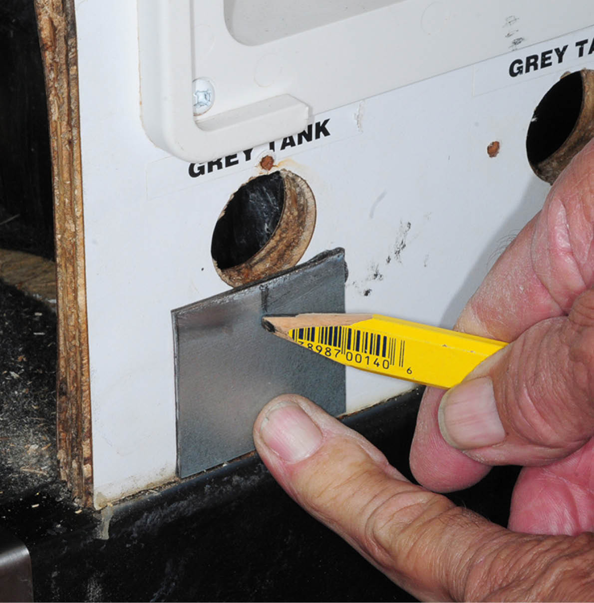
After cleaning the surface with alcohol, galvanized plates were measured and marked for covering the holes, which were way too big for the new cables.
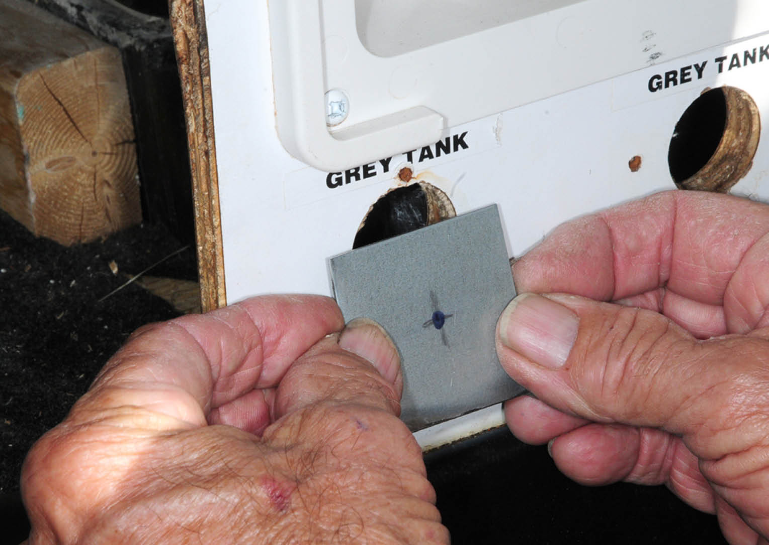
The backing was removed from the two-face tape and the plates were “stuck” to the wall, covering the holes. VHB tape is really strong stuff and the plates will stick forever.
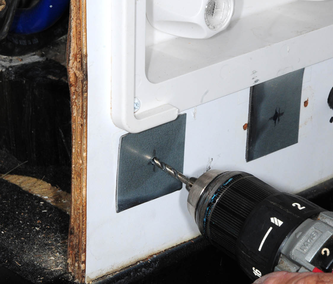
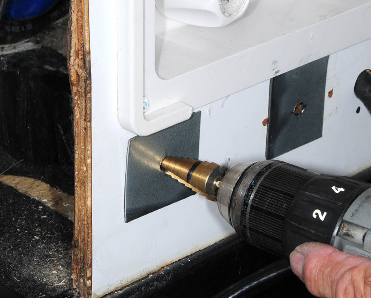
Once the plates were in place, a pilot hole was drilled in the center and then a 5/8-inch hole was cut with a step drill to accommodate the cable assembly.
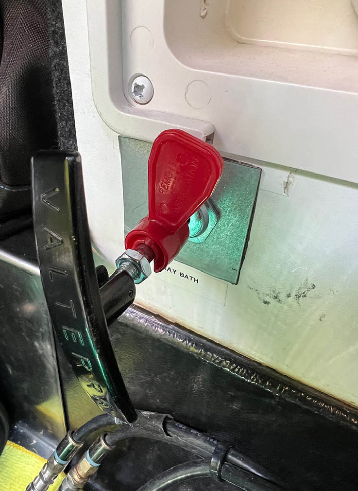
Once the cable was connected to the valve, the red tab was removed and a label identifying the corresponding holding tank was printed and attached to the wall.
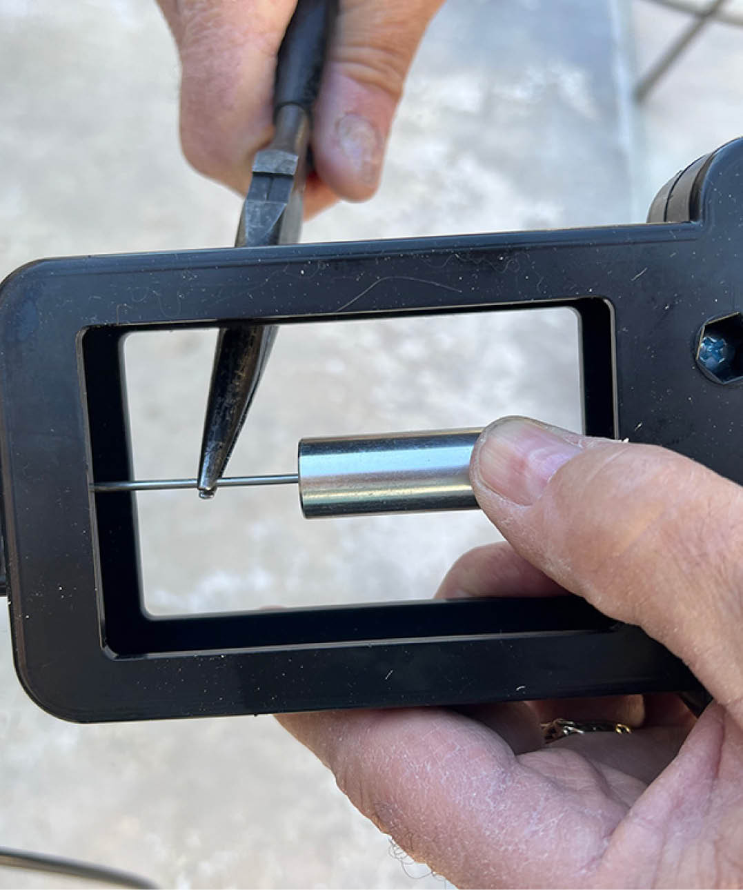
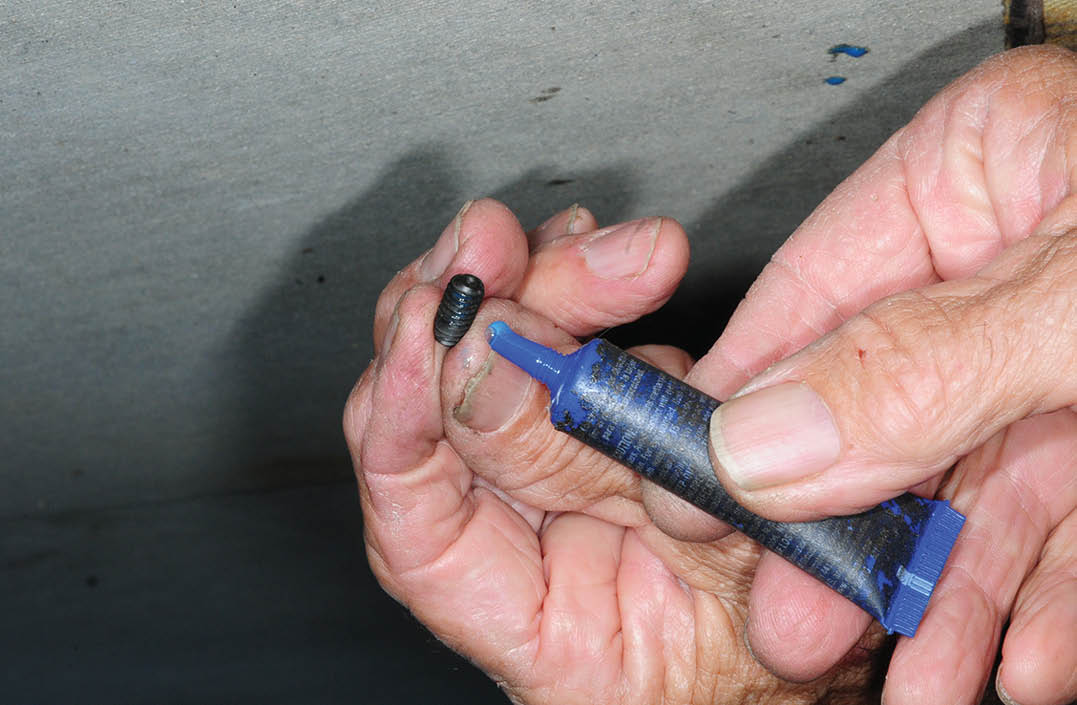
Blue Loctite thread sealer was applied to the coupler set screw before it was tightened with the provided Allen wrench to jam the internal wire. This wire will have to be removed if the valve needs replacement down the road and using red Loctite will make that process almost impossible (and probably lead to cutting the cable).
Already a Subscriber? Click here for Access to the Full Issues.